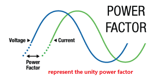
represent the unity power factor.
Hello dear readers. In this post on Solsarin we are going to talk about ” represent the unity power factor “. Continue reading to find the answer. please write your comment, Thank you for your attention.
AC circuits which contain resistance and capacitance or resistance and inductance, or both, also contain real power and reactive power. So in order for us to calculate the total power consumed, we need to know the phase difference between the sinusoidal waveforms of the voltage and current.
In an AC circuit, the voltage and current waveforms are sinusoidal so their amplitudes are constantly changing over time. Since we know that power is voltage times the current (P = V*I), maximum power will occur when the two voltage and current waveforms are lined up with each other. That is, their peaks and zero crossover points occur at the same time. When this happens the two waveforms are said to be “in-phase”.
The three main components in an AC circuit which can affect the relationship between the voltage and current waveforms, and therefore their phase difference, by defining the total impedance of the circuit are the resistor, the capacitor and the inductor.
The impedance, (Z) of an AC circuit is equivalent to the resistance calculated in DC circuits, with impedance given in ohms. For AC circuits, impedance is generally defined as the ratio of the voltage and current phasor’s produced by a circuit component. Phasor’s are straight lines drawn in such a way as to represents a voltage or current amplitude by its length and its phase difference with respect to other phasor lines by its angular position relative to the other phasor’s.
AC circuits contain both resistance and reactance that are combined together to give a total impedance (Z) that limits current flow around the circuit. But an AC circuits impedance is not equal to the algebraic sum of the resistive and reactive ohmic values as a pure resistance and pure reactance are 90o out-of-phase with each other. But we can use this 90o phase difference as the sides of a right angled triangle, called an impedance triangle, with the impedance being the hypotenuse as determined by Pythagoras theorem.
This geometric relationship between resistance, reactance and impedance can be represented visually by the use of an impedance triangle as shown.
MORE POSTS:
- capital one employment verification
- when did tigers first become endangered
- what percent alcohol is skyy vodka
- when does fog usually form in inlets and bays?
- how did early english drama develop?
Note that impedance, which is the vector sum of the resistance and reactance, has not only a magnitude (Z) but it also has a phase angle (Φ), which represents the phase difference between the resistance and the reactance. Also note that the triangle will change shape due to variations in reactance, (X) as the frequency changes. Of course, resistance (R) will always remain constant.
We can take this idea one step further by converting the impedance triangle into a power triangle representing the three elements of power in an AC circuit. Ohms Law tells us that in a DC circuit, power (P), in watts, is equal to the current squared (I2) times the resistance (R). So we can multiply the three sides of our impedance triangle above by I2 to obtain the corresponding power triangle as:
Real Power P = I2R Watts, (W)
Reactive Power Q = I2X Volt-amperes Reactive, (VAr)
Apparent Power S = I2Z Volt-amperes, (VA)
Real Power in AC Circuits
Real power (P), also known as true or active power, performs the “real work” within an electrical circuit. So Real power, measured in watts, defines the power consumed by the resistive part of a circuit. Then real power, (P) in an AC circuit is the same as power, P in a DC circuit. So just like DC circuits, it is always calculated as I2*R, where R is the total resistive component of the circuit.
As resistances do not produce any phasor difference (phase shift) between voltage and current waveforms, all the useful power is delivered directly to the resistance and converted to heat, light and work. Then the power consumed by a resistance is real power which is fundamentally the circuits average power.
To find the corresponding value of the real power the rms voltage and current values are multiplied by the cosine of the phase angle, Φ as shown.
Real Power P = I2R = V*I*cos(Φ) Watts, (W)
But as their is no phase difference between the voltage and the current in a resistive circuit, the phase shift between the two waveforms will be zero (0).
Understanding The Power Factor
Energy is needed and utilized everywhere in the world. From the point of view of convenience, efficiency and economy, it is best that we generate, transmit and distribute it in electrical form before it is converted into the required one by suitable equipments. For the same reasons of economy and efficiency, we use AC rather than DC. Practically, we generate, transmit and distribute energy in AC form almost exclusively. DC is used either in DC applications (DC machines and electronic circuits) or in HVDC transmission links.
Wherever AC power is utilized, the question of power factor arises itself.
Power Factor
- Defined as ‘the cosine of the angle between the voltage and current‘.
- In AC circuit, the voltage and current are ideally in phase.
- But practically, there exists a phase difference between them.
- The cosine of this phase difference is termed as power factor.
- It can be defined and mathematically represented as follows:
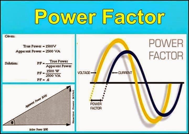
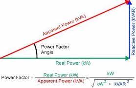
Power Factor = cosɸThe fig. (b) is called as Power Triangle
Here, VI sinɸ = Reactive power (in VAR)
VI cosɸ = Active power (in Watts)
VI = Apparent power (in VA)
PF = cosɸ = Active Power (W) / Apparent Power (VA)The fig. (c) is called as Impedance Triangle
Here, R = Resistance, X = Reactance, Z = Impedance
Z2 = R2 + X2
PF = cosɸ = R/Z
The Power Factor can be lagging, leading or unity.
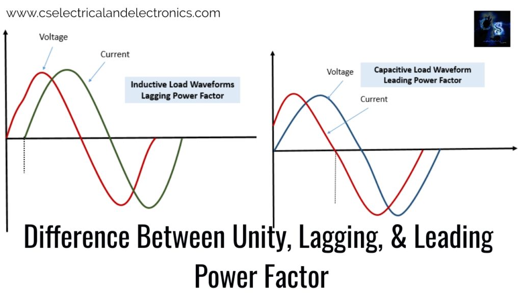
Lagging Power Factor
- When current lags behind the voltage, the power factor of the circuit is called ‘Lagging’
- When the circuit is inductive, the pf is lagging.
- The loads such as induction motors, coils, lamps, etc are inductive and have Lagging pf.
Leading Power Factor
- When current leads the voltage (or voltage lags behind the current), the power factor of the circuit is called ‘Leading’.
- When the circuit is capacitive, the pf is leading.
- Capacitive loads such as Synchronous condensers, capacitor banks etc draw leading current. Such circuits have leading power factor.
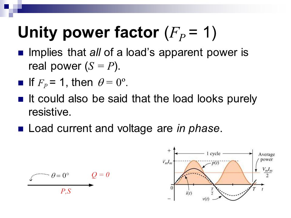
Unity Power Factor
- Power factor is unity (i.e. 1) for ideal circuits.
- When current and voltage are in phase, PF = 1
- Power factor cannot be more than unity.
- Practically, it should be as close to unity as possible.
If power factor is low, following problems are encountered:
Effects Of Low Power Factor
- Load Current
Power in an AC circuit can be given as: P = VI cosɸ
Therefore, cosɸ = P / VI
I ∝ 1 / cosɸ
Similar relationship can be derived for 3 phase circuit too. We can see that current is inversely proportional to pf.
For example, consider that we want to transfer 10 kVA power at 100 V
If PF = 1,
I = P / (V cosɸ) = 10000 / (100 x 1) = 100 A
If PF = 0.8,
I = P / (V cosɸ) = 10000 / (100 x 0.8) = 125 A
Hence, the current drawn is higher for low power factor.
- Losses: As stated above, for low pf, the current drawn is high. Hence copper losses (I2R losses) will also be high. This decreases the efficiency of the equipment.
- Overheating of the equipment: I2R losses produce heat (Joule’s law). Hence, the temperature rise will be relatively more for low PF which will further increase the stress on the insulation.
- Size of conductor: Low power factor causes higher load current. If the load current increases, the size of the conductor required will also increase. This will further increase the conductor cost.
- kVA rating of the machine: Machines are not rated in kW while manufacturing because the power factor of supply is unknown. Instead, they are rated in kVA.
According to definition, Cosɸ = Active power (kW) / Apparent power (kVA)
Hence, kVA rating = 1 / cosɸ
Therefore, for low pf, equipment of larger kVA rating is needed. But larger kVA rating means larger size of the equipments. If size increases, the cost also increases. - Voltage Regulation: It is defined as the difference between sending and receiving end voltage per unit sending end voltage. When power is transferred from one end to another, the voltage drops due to several reasons. This voltage drop should be within permissible limits.
P = VI cosɸ , Therefore I ∝ 1 / V
For low power factor, current will be more and hence voltage drop will be increased. Hence, the voltage regulation at low power factor is poor. - Active and Reactive power (Power Transfer Capacity): Active and reactive power both are transferred over the line together. Active power is needed for supplying the load. Reactive power is needed to maintain the voltage of the line. But if reactive power is more, then active power transferred is decreased. For low pf, active power is low because, cosɸ = Active power (W) / Apparent power (VA). This results in uneconomic operation.